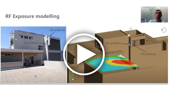
A growing number of 5G small cells are being deployed in the C-band where the antennas are implemented on shorter poles. This requires additional evaluation of electromagnetic field exposure. IXUS provides a complete solution for network operators and compliance assessment companies to establish and maintain RF safety compliance.
Dr. Danie Ludick, CEO of IXUS, recently presented a webinar (view the recording here) on how ray-tracing can be used to generate accurate compliance boundaries for 5G antennas. He discussed how the IXUS RF safety analysis suite of software measures the RF fields around the antennas. Additionally, he explained how the company’s field calculation engine works.
“The software is designed to produce reports as accurately and swiftly as possible,” Dr. Ludick said. “When you model these environments in our tool, our job at IXUS is to make sure that, when you plug in a certain antenna model, you get something that depicts the behavior of that system as accurately as possible,” he added.
Dr. Ludick showed several simulation approaches that can be used to model 5G antennas. The full-wave approach, he said, was too expensive to simulate each potential beam position. Another approach of mechanically tilting a single beam is also not used by IXUS because it is not accurate enough. The approach adopted by IXUS involves traffic envelope ray-tracing. He explained why this is the optimal solution.
“If we have an antenna and we have radiation properties and horizontal and vertical field patterns, then we can represent that antenna as a linear array of point sources,” Dr. Ludick said. “We calculate the fields that are emitted from those point sources in an approach called ray-tracing. We use those rays to calculate the field at any point near the antenna, even in the near field.” Using limits set by the FCC, the IXUS software calculates the exclusion zone, or the area that is unsafe from an RF radiation standpoint.
For modeling 5G antennas, IXUS uses a traffic envelope pattern from the antenna manufacturer. The horizontal and the vertical traffic envelope is used to do an interpolation to form a three-dimensional element pattern, which is used in the ray-tracing approach. The result of the antenna modeling is a 3D exclusion zone that can accommodate any position of where the traffic beam might be situated.
“The key step of the antenna modeling is where we synthesize the correct behavior that the antenna manufacturers supply,” Dr. Ludick said. “We use an intelligent optimization approach to calculate the number of elements and the spacing and the scaling of each one. As a result, the patterns that we generate using our ray-tracing approach match the patterns that the manufacturer has provided.”
The gain is also scaled as part of the model so that it is in alignment with the traffic envelope beam. Power can be adjusted based on how conservative the user wants the model to be. Dr. Ludick also explained how the results of the ray tracing can be verified.
“You need to be sure that your analysis is based on antenna models that are sound when it comes to calculations,” Dr. Ludick said. “We take pride in making sure we offer that. We do that by the very efficient use of our ray-tracing methodology in combination with the traffic envelope patterns that manufacturers provide to build a model that can be used for these simulations quite nicely.”
For more information and to watch this webinar on-demand, please click here.
By J. Sharpe Smith, Inside Towers Technology Editor


Reader Interactions